

4-wire MAP sensor and its faults
New product

The 4-wire MAP sensor and its flaws
Hi there, today I am going to talk about the 4-wire MAP sensor. This has 4 cables because inside it has an additional sensor to the pressure which is the air temperature. Then the pressure sensor behaves the same as the three-wire one, that is, as the vacuum in the intake manifold increases, the voltage of the MAP sensor decreases proportionally. Also, as the vacuum decreases, the MAP sensor voltage increases proportionally.
Publicidad.
In the PWM type, something similar happens, but it decreases or increases in the ignition cycle.
How to test a 4-wire MAP sensor
It is quite simple.Before testing any electrical component, inspect the wiring and connectors for damage.
Move the connectors to make sure they are firmly engaged.
When testing the sensor, use a high input impedance digital volt-ohmmeter. Insert the tester cables through the back of the connector. Do not disconnect the electrical harness.
Inspect the vacuum hose connections at the sensor and throttle body. Repair or replace the hoses if any of the hoses are cracking or if you notice that they are leaking.
For the next step, do not disconnect the sensor connector, it must remain plugged in.
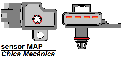
See the following figure representing the sensor diagram:

Pressure side test
Check the MAP sensor output voltage by inserting the negative lead of the voltmeter into the back of terminal 1 and the positive test lead through the back of the terminal of the harness connector, station 4.
With the ignition switch in the ON position and the engine off, the pressure sensor output voltage should be 4-5 volts.
Start the engine and let it idle at normal operating temperature. The output voltage should drop to 1.5-2.1 volts.
If there is no voltage, do the following:
Test the MAP sensor supply voltage at sensor connector terminals 3 and 1 with the ignition ON. If there is no voltage try to see if there is a broken wire between the connector and the computer or ECM relay is operating.
Publicidad.
You can use an ohmmeter, to check the wiring harness between the connector and the computer. Repair the wire harness if you notice an open circuit or if infinite resistance is detected.

Temperature side test
Remove the connector from the sensor and turn the ignition on.Measure between terminals 1 and 2.5V must exist which is the reference voltage.
Turn the ignition key to the OFF position and reconnect the sensor.
Put the ignition back in the ON position and measure between 1 and 2. At 36 degrees outside air temperature there should be about 1.6V.
If there is no voltage, try to see if there is a broken wire between the connector and the computer or ECM relay is operating.
You can use an ohmmeter, to check the wiring harness between the connector and the computer. Repair the wire harness if you notice an open circuit or if infinite resistance is detected.
¿Do you have questions or concerns??
Questions or suggestions can use the form below and I will gladly answer them.
Follow me on my Social Networks
 |  |
Written by Dennis García.
Chica Mecánica
More info
Excelente
Gran post
Ask a question
NO registration required!
6 Question(s) answered
If the question you have has not yet been answered here, use the form below to ask something about this addon.
- Asked by asdasd
on 10/07/2020 Si luego de leer nuestro articulo aun tiene dudas, puede hacer su pregunta utilizando el siguiente formulario. Answer:
Asi mismo es asdasd. Puedes preguntar sin problemas. - Asked by miguel
on 12/04/2020 quisiera saber si el sensor maf de fiesta move es alimentado con 12 volts, y como es su coneccion . el sensor tiene unos numeros identificando los pines 1-2-3-4 Answer:
Caramba Miguel, no tengo diagrama de fiesta. - Asked by Wilfredo
on 12/15/2020 Como puedo identificar el cable de señales de presion y el cable de señal de temperatura que vienen desde el computador al sensor, ya que cortaron el conector y los cables cuelgan, ya que solo puedo identificar masa, los otros 3 cables me marcan 5 volts. Es ahí mi confusión, si puedes ayudarme te lo agradecería mucho... Answer:
Con el pin-out de la computadora, o organizando por color y colocar una resistencia de 1k por par de cables para ver los resultados. Pero es mejor con el diagrama eléctrico. - Asked by Andres beltran
on 06/19/2021 Se an desconectado los cables deseo saver como ubicarlos para conectarlos nueva mente Answer:
Caramba, en el artículo están definidos los voltajes. Con un multímetro puedes identificar y reconectar. - Asked by GUSTAVO
on 10/18/2021 Buen dia, Mi Zafira comenzo a perder potencia en ruta, no podia superar 60 km, cuando me detube y volvi a 1ra marcha se puso mas lentoba pesar que el cuenta revoluciones subia de 2000, 2500 y 3000 rpm con un avace lento hasta maximo de 20 a 30 km maximo. Cambie sensor Tps y no mejoro nada. Answer:
Mmmmm Si las RPM estan subiendo y no hay marcha, es muy posible que la el sistema de embrague este deslizando. Esto puede deberse a que hay fuga de aceite por el eje de la caja o porque esta muy desgastado el plato y el disco. - Asked by Eduardo Zabala
on 10/20/2021 Hola tengo un problema con mi Mazda 3 el conector del sensor map está averiado lo intente cambiar y no se la posición del cableado osea la continuidad que le corresponde ah cada cable me podrías ayudar a resolver ese problema ? Gracias Answer:
Con el diagrama del carro es posible. Pero no lo tengo a disposición.
 |
If the download link redirects to another product that is not described in the article or is broken, report it using our Reporting Form